What Is a Power Transformer?
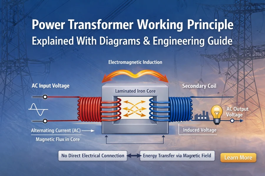
A power transformer is a static electrical device that transfers electrical energy between circuits through electromagnetic induction. It is used primarily in transmission and distribution systems to step voltage up or down efficiently.
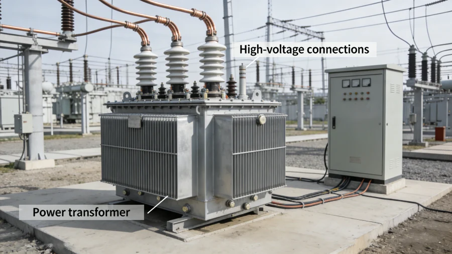
Power transformers are essential components of modern power grids, industrial plants, renewable energy systems, and data centers.
They operate based on the fundamental law discovered by Michael Faraday — electromagnetic induction.
The Core Principle: Electromagnetic Induction
The working principle of a power transformer is based on Faraday’s Law of Electromagnetic Induction, which states:
When a changing magnetic field passes through a conductor, it induces an electromotive force (EMF) in that conductor.
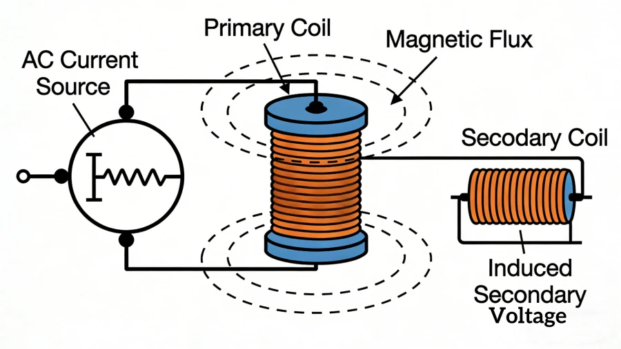
In a transformer:
-
Alternating current (AC) flows into the primary winding.
-
This current creates a changing magnetic flux in the iron core.
-
The magnetic flux links to the secondary winding.
-
A voltage is induced in the secondary winding.
No direct electrical connection exists between primary and secondary circuits. Energy transfer occurs through magnetic coupling.
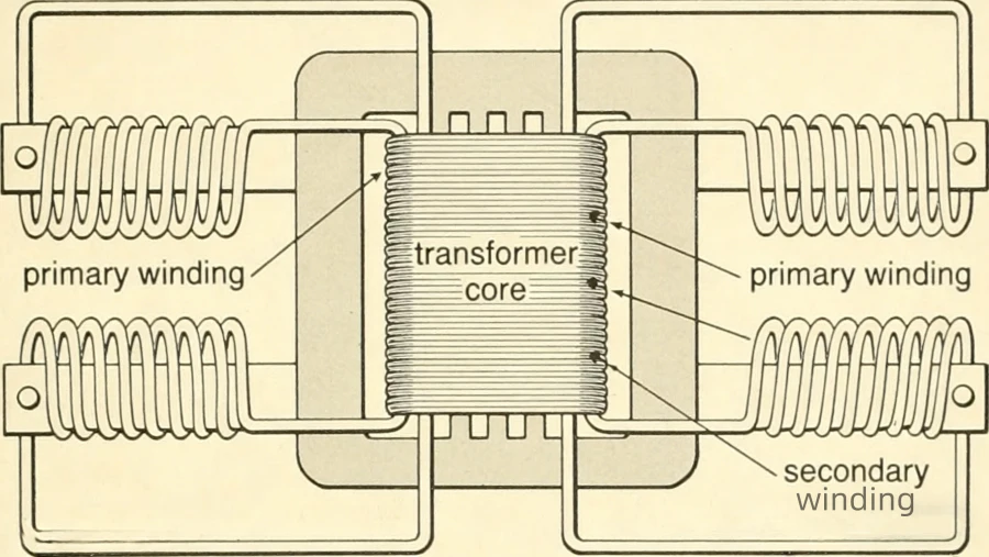
Basic Transformer Construction
A power transformer consists of three main parts:
1️⃣ Magnetic Core
-
Laminated silicon steel
-
Reduces eddy current losses
-
Provides magnetic path
2️⃣ Primary Winding
-
Connected to input voltage
-
Creates magnetic flux
3️⃣ Secondary Winding
-
Delivers transformed voltage
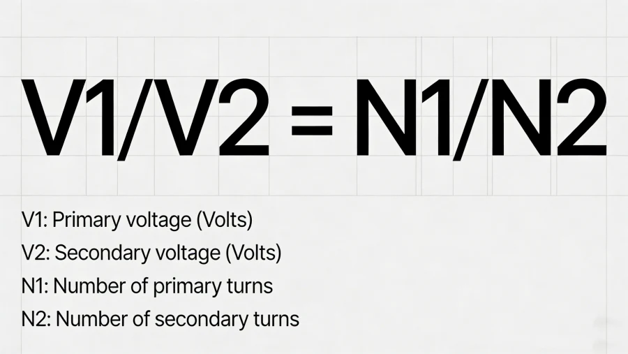
Voltage Transformation Formula
The voltage ratio depends on the turns ratio:
V1/V2=N1/N2
Where:
-
V₁ = Primary voltage
-
V₂ = Secondary voltage
-
N₁ = Primary turns
-
N₂ = Secondary turns
If N₁ > N₂ → Step-down transformer
If N₁ < N₂ → Step-up transformer
This simple mathematical relationship explains how power transformers adjust voltage levels in transmission systems.
How Energy Is Actually Transferred
Many beginners misunderstand this:
Energy is not transferred through the core itself.
Energy transfer occurs due to:
-
Magnetic flux coupling
-
Time-varying magnetic field
-
Induced secondary current under load
When a load is connected:
-
Secondary current flows
-
It creates opposing flux
-
Primary current increases automatically
-
System remains magnetically balanced
This self-regulating behavior makes transformers highly efficient.
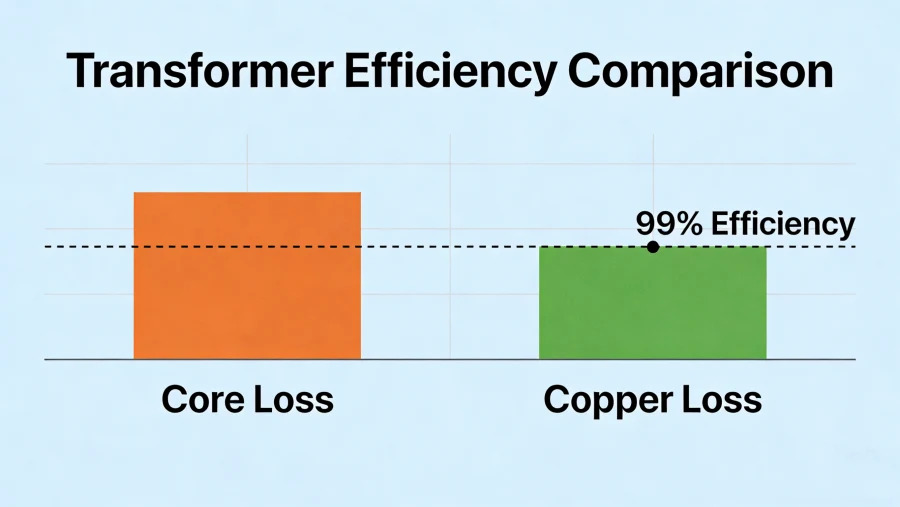
Transformer Efficiency and Real-World Behavior
Power transformers typically operate at 98% to 99.5% efficiency in utility applications.
Losses occur in two major forms:
1️⃣ Core Loss (No-Load Loss)
-
Hysteresis loss
-
Eddy current loss
-
Occurs whenever transformer is energized
2️⃣ Copper Loss (Load Loss)
-
I²R losses in windings
-
Increases with load
Modern transformer design optimizes:
-
Core material quality
-
Conductor cross-section
-
Cooling methods
Magnetic Flux Behavior Inside the Core
Magnetic flux follows a closed loop inside the laminated steel core.
Important concepts:
-
Flux density (Tesla)
-
Magnetic saturation
-
B-H curve
-
Magnetizing current
If core saturates:
-
Current increases sharply
-
Heating occurs
-
Harmonic distortion rises
Proper core design ensures operation below saturation limits.
Why Transformers Only Work with AC
Transformers require changing magnetic flux.
Direct current (DC) produces constant magnetic flux →
No induced voltage in secondary →
Core saturation risk.
This is why power transformers are designed strictly for AC systems.
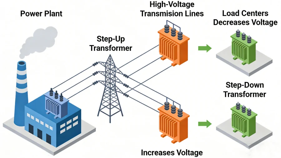
Step-Up vs Step-Down Transformers in the Grid
In transmission systems:
-
Generation voltage ≈ 11–25 kV
-
Step-up to 132 kV / 220 kV / 400 kV
-
Long-distance transmission
-
Step-down near load centers
High voltage reduces current and minimizes transmission losses.
Get More:What Is a Substation Transformer? A Practical Guide for Power Projects

Real Engineering Example
Industrial Facility Case:
Input voltage: 10 kV
Required voltage: 400 V
Load demand: 800 kVA
Using transformer principle:
Turns ratio = 10,000 / 400 = 25:1
Proper winding ratio ensures stable voltage transformation.
Practical Design Factors That Affect Working Principle
In real engineering projects, additional elements affect performance:
-
Leakage reactance
-
Short-circuit impedance
-
Harmonics
-
Temperature rise
-
Cooling method (ONAN / ONAF)
-
Insulation class
These factors influence transformer stability and lifespan.
Advanced Concept: Magnetic Coupling & Leakage Flux
Not all magnetic flux links both windings.
Leakage flux causes:
-
Voltage regulation deviation
-
Impedance effects
-
Short-circuit current limitation
Engineers intentionally design leakage reactance for system protection.
Learn More:What Is an Electrical Transformer? Function, Design, and Working Principle
Why Understanding the Working Principle Matters for Procurement
For project engineers and buyers, understanding transformer fundamentals helps:
-
Avoid oversizing
-
Prevent under-specification
-
Improve system efficiency
-
Reduce lifecycle cost
-
Evaluate supplier technical claims
Procurement decisions should be based on physics, not just price.
Common Misconceptions About Power Transformers
❌ Transformers generate electricity
✔ They only transfer energy
❌ Power factor changes voltage ratio
✔ Voltage ratio depends only on turns
❌ Efficiency is constant
✔ Efficiency varies with load profile
Frequently Asked Questions
What is the main law behind transformer operation?
Faraday’s law of electromagnetic induction.
Why does transformer current increase under load?
Secondary load creates opposing flux, increasing primary current automatically.
What limits transformer capacity?
Thermal limits, insulation strength, and cooling capability.
Read More:What Is a Pad Mounted Transformer? Complete Guide with Types and Uses
Conclusion
The power transformer working principle is fundamentally simple:
-
AC current
-
Changing magnetic flux
-
Induced voltage
-
Energy transfer via magnetic coupling
However, real-world engineering applications involve advanced considerations such as flux density control, impedance design, cooling optimization, and loss minimization.
A solid understanding of transformer physics enables better system design, safer installations, and more intelligent procurement decisions.
If you are specifying or sourcing power transformers for industrial, renewable, or utility applications, understanding these principles ensures long-term reliability and optimal performance.