
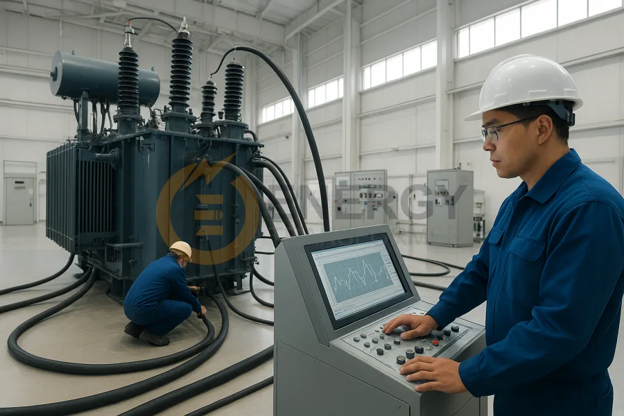
Medium voltage (MV) power transformers are the silent workhorses of electrical distribution networks. Operating in the 10 kV to 35 kV range, they serve as critical links between high-voltage transmission systems and low-voltage distribution grids. While they are designed for decades of service, their reliability depends on proactive monitoring, rigorous testing, and proper asset management.
Routine testing is not simply a regulatory requirement—it is an investment in operational continuity, equipment longevity, and system efficiency. An in-depth diagnostic program helps uncover hidden defects, benchmark performance against factory data, and create a digital health record that supports predictive maintenance. This guide provides a step-by-step framework for engineers and technicians in North America, Europe, and beyond, offering best practices for medium voltage transformer diagnostics, testing methodology, and structured data logging.
1. Establishing the Foundation: MV Transformer Test Setup
Every successful diagnostic program begins with thorough preparation. Incorrect setup or incomplete planning can compromise both safety and test accuracy.
Essential Transformer Types
-
Single-phase (10–167 kVA): Often used in rural distribution networks.
-
Three-phase (50–1000 kVA): Standard in industrial and urban distribution systems.
Precision Testing Instruments
-
Digital Multi-Meter (DMM): Voltage, continuity, and resistance checks.
-
Clamp-on Ammeter: Real-time current measurements without interrupting the circuit.
-
Digital Power Analyzer: Voltage, current, real power (kW), apparent power (kVA), power factor, and harmonic distortion.
-
Insulation Resistance Tester (Megger): Typically rated at 2.5 kV or 5 kV for insulation integrity checks.
-
Winding Resistance Meter: To assess winding DC resistance.
-
Earth Ground Tester: Verifies grounding compliance and safety.
Load & Thermal Measurement Tools
-
Variable Resistive Load Bank: Simulates controlled load conditions.
-
Infrared Thermometer / Thermal Camera: Detects hotspots in windings, bushings, and terminations.
-
Thermocouples: Provides precise monitoring of winding and oil temperatures.
Safety Gear (PPE)
-
Arc-rated clothing, insulated gloves, dielectric boots, face shields, and insulated mats. Always test with at least two qualified personnel present.
Learn More:Transformer Efficiency Standards and Loss Analysis: A Complete Guide (IEC & DOE Compliant)

2. No-Load (Open-Circuit) Test – Measuring Core Losses
The no-load test evaluates the iron (core) losses due to hysteresis and eddy currents. Since these losses are constant whenever the medium voltage transformer is energized, abnormal values can indicate problems such as lamination deterioration or partial winding shorts.
Procedure
-
Secondary windings remain open.
-
Rated voltage is applied to the HV winding.
-
Record input voltage, current, and power with a digital power analyzer.
Data Log Example
| Transformer ID | Test Date | Rated HV (V) | Rated LV (V) | Measured HV (V) | Current (A) | No-Load Power (W) | Remarks |
|---|---|---|---|---|---|---|---|
| ET-500kVA-13.8kV | 2025/8/21 | 13,800 | 480 | 13,800 | 0.55 | 150 | Stable reading, low PF confirms core magnetization |
Analysis:
-
A sudden increase in no-load losses compared to factory test data signals core degradation or winding insulation faults.
-
Low power factor confirms magnetization dominance.
3. Load (Short-Circuit) Test – Evaluating Copper Losses & Regulation
The load test simulates real-world conditions to measure copper (I²R) losses and voltage regulation.
Procedure
-
Connect secondary to a resistive load bank.
-
Gradually load from 25% → 100% capacity.
-
At each increment, record voltage, current, and input/output power.
Sample Data Log
| Load (%) | V_sec (V) | I_sec (A) | Input Power (kW) | Output Power (kW) | Efficiency (%) | Voltage Regulation (%) |
|---|---|---|---|---|---|---|
| 25% | 479 | 240 | 126 | 125 | 99.2 | - |
| 50% | 477 | 480 | 252 | 250 | 99.2 | - |
| 75% | 475 | 720 | 378 | 375 | 99.2 | - |
| 100% | 473 | 960 | 504 | 500 | 99.2 | 1.46 |
Analysis:
-
High regulation values = excessive impedance.
-
Low efficiency = potential shorted turns, loose connections, or poor design.
Read More:How Transformers Regulate Voltage: From Substations to Your Power Infrastructure
4. Insulation Resistance (IR) & Polarization Index (PI) Testing
Insulation degradation is the leading cause of medium voltage transformer failure. IR and PI testing measure insulation resistance and its ability to polarize over time.
Procedure
-
De-energize and ground all windings.
-
Apply 2.5–5 kV DC test voltage using a Megger.
-
Record resistance at 1 min and 10 min.
-
Calculate PI = R10min / R1min.
Interpretation:
-
PI > 2.0: Excellent condition.
-
PI 1.0–2.0: Possible moisture contamination.
-
PI < 1.0: Severe insulation weakness.
5. Transformer Turns Ratio (TTR) Test
Confirms that the turns ratio aligns with nameplate data and that there are no shorted or open turns.
Formula:
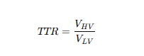
Deviation >0.5% from nameplate = winding defect or incorrect connection.
6. Winding Resistance Test
DC resistance testing detects broken strands, loose joints, or local heating issues.
Procedure
-
Use a low-resistance ohmmeter.
-
Measure each phase.
-
Compare against factory benchmarks.
Warning: Significant deviation = damaged conductor or poor brazing.
Get More:Basic Transformer Ratings Explained kVA, Voltage, Frequency & Impedance for Buyers and Engineers
7. Temperature Rise Test – Long-Term Thermal Health
Medium voltage transformers fail prematurely when cooling systems underperform. This test validates compliance with ANSI/IEEE C57.12 and IEC 60076 standards.
Procedure
-
Operate medium voltage transformer at full load for ≥6 hours.
-
Monitor top-oil and winding temperatures with thermocouples and IR imaging.
-
Ensure rise above ambient does not exceed standard limits.
8. Dissolved Gas Analysis (DGA) – Advanced Condition Monitoring
While not always part of routine tests, DGA is essential for medium voltage transformers in critical applications. It detects gases produced by oil decomposition due to arcing, overheating, or insulation breakdown.
Key Gases Monitored:
-
Hydrogen (H₂): Partial discharges.
-
Methane (CH₄), Ethane (C₂H₆), Ethylene (C₂H₄): Overheating.
-
Acetylene (C₂H₂): Severe arcing.
Trend analysis provides early warnings before catastrophic failure.
Read More:What Happens When a Transformer Blows
9. Data Logging & Digital Asset Management
Modern testing is incomplete without structured data recording. Test results should be digitized into asset management software or exported to Google Sheets / Excel for trend analysis.
Benefits of Data Logging:
-
Creates a digital fingerprint of each transformer.
-
Enables trend-based diagnostics instead of isolated evaluations.
-
Supports predictive maintenance strategies.
Conclusion – From Diagnostics to Proactive Asset Management
Medium voltage transformers are high-value assets that demand proactive care. By combining routine testing, advanced diagnostics, and structured data logging, organizations can:
-
Prevent Outages: Catch failures before they occur.
-
Optimize Efficiency: Maintain high efficiency to reduce losses.
-
Extend Service Life: Preserve medium voltage transformer health with predictive maintenance.
-
Ensure Compliance: Meet ANSI/IEEE, IEC, and local safety regulations.
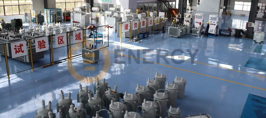
Our Energy Transformer products are engineered with these diagnostic principles in mind, undergoing rigorous factory acceptance testing (FAT) and routine condition monitoring to guarantee dependable performance across diverse grid environments in North America, Europe, and beyond.