As the central hub of modern power systems, Power transformer operation extends far beyond simple voltage conversion. A thorough understanding of its principles, construction, and design considerations is essential for mastering power transmission and distribution technologies. This article systematically analyzes transformer working principles, core components, loss mechanisms, and advanced design concepts.
I. Electromagnetic Induction: The Physical Foundation of Transformer Operation
-
The Central Role of Faraday's Law:
The essence of electrical transformer operation lies in Faraday's Law of Electromagnetic Induction, discovered by Michael Faraday. This law states: The electromotive force (EMF) induced in a closed circuit is equal to the rate of change of magnetic flux linkage through that circuit. Mathematically:e = -N * dΦ/dt, wheree= induced EMF (volts),N= number of coil turns, anddΦ/dt= rate of change of magnetic flux (webers/second). The negative sign indicates the induced EMF always opposes the change in flux (Lenz's Law). -
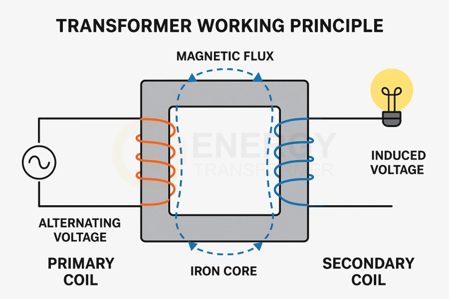
The Magic of Mutual Induction:
Electrical transformers rely fundamentally on mutual induction. When alternating current (AC) flows through the primary winding, it generates a time-varying magnetic flux (Φ). This flux is efficiently confined and channeled by a magnetic core, typically constructed from laminated ferromagnetic material (silicon steel). When this flux links with the physically isolated but magnetically coupled secondary winding, Faraday's Law induces an AC EMF in the secondary winding. -
Self-Induction: Role and Limitation:
The changing current in the primary winding also induces an EMF in itself (self-induction), manifesting as the winding's inductance. While self-induction is crucial for establishing the magnetic field and limiting current surges, mutual induction is the core mechanism for energy transfer. -
The Turns Ratio Law: Key to Voltage Transformation:
If the primary and secondary windings are perfectly linked by the same alternating flux (ideal coupling), the induced EMF (e) in each coil is strictly proportional to its number of turns (N). Therefore, the voltage transformation ratio equals the turns ratio:V₂ / V₁ ≈ E₂ / E₁ = N₂ / N₁ = K
Where:-
V₁,E₁,N₁: Primary winding input voltage, induced EMF, number of turns. -
V₂,E₂,N₂: Secondary winding output voltage, induced EMF, number of turns. -
K: Turns Ratio. -
N₂/N₁ > 1(K > 1) = Step-Up Transformer. -
N₂/N₁ < 1(K < 1) = Step-Down Transformer.
-
II. Key Factors Determining Transformer Performance
-
Core Material: The Magnetic Highway:
-
High Permeability (μ): Silicon steel (electrical steel) is widely used due to its high permeability, significantly increasing flux density (
B) for a given magnetizing force (H) (B = μH), reducing the exciting current needed to establish working flux. -
Low-Loss Design: Silicon steel often contains silicon (3-5%) to increase resistivity, reducing eddy current loss. It is cold-rolled with specific grain orientation (GOES - Grain-Oriented Electrical Steel) to optimize the magnetization direction, drastically lowering hysteresis loss. Modern amorphous metal alloys offer even lower hysteresis loss, ideal for high-efficiency distribution transformers.
-
Laminated Structure: The core is built from thin, insulated silicon steel laminations to interrupt large eddy current paths, confining them within individual laminations – a critical process for minimizing core loss.
-
-
AC Supply Frequency (f): The Engine of Change:
-
Induced EMF
e ∝ N * dΦ/dt. The rate of flux changedΦ/dtis directly proportional to the supply frequencyf. Therefore, for the same flux density, higher frequency results in higher induced voltage, or allows for a smaller core cross-sectional area. Global power grids primarily use 50Hz or 60Hz standard frequencies.
-
-
Winding Coupling: Guaranteeing Efficiency:
-
Tight Coupling is essential for efficient transformation. Flux generated by the primary winding should link as completely as possible with the secondary winding (main flux
Φ_m). -
Leakage Flux (
Φ_leakage) is flux that fails to link effectively, causing leakage inductance, which increases voltage drop and losses, reducing efficiency and voltage regulation. -
Winding Arrangement: Techniques like interleaved windings (primary and secondary layers alternated), special winding methods (helical, continuous disc), and optimized core structures (shell-type often offers tighter coupling than core-type) are engineering solutions to minimize leakage flux and improve the coupling coefficient.
-
Read More:The Complete Transformer Wiring Guide 2025
III. Anatomy of Transformer Core Construction
-
Core: The Flux Director:
-
Material: High-permeability, low-loss silicon steel (Cold-Rolled Grain-Oriented - CRGO is standard).
-
Structure:
-
Core Type: Windings surround the core limbs. Relatively simple structure, better cooling, easier maintenance. Widely used for high-voltage, high-power transformers.
-
Shell Type: Core surrounds the windings. Higher mechanical strength, lower leakage flux, symmetrical magnetic path, but slightly more complex manufacturing/repair. Common for medium-low voltage, special applications (furnace transformers, rectifier transformers), and compact, high-efficiency designs.
-
Wound Core: Continuous strip of silicon steel wound into a core. Seamless magnetic path significantly reduces no-load loss and noise. Primarily used in high-efficiency distribution transformers.
-
-
-
Windings: The Current Carriers:
-
Material: High-conductivity electrolytic copper (standard) or aluminum.
-
Types:
-
Concentric: Low Voltage (LV) and High Voltage (HV) windings are concentrically placed over the core limb (LV often inside for easier HV insulation). Predominantly used in core-type transformers.
-
Interleaved (Sandwich): LV and HV windings are alternately stacked along the height of the core limb. Mainly used in shell-type transformers, reducing leakage inductance and axial short-circuit forces.
-
-
Key Considerations: Conductor cross-section (current capacity), number of turns (turns ratio), insulation design (voltage withstand, cooling), mechanical strength (withstand short-circuit forces).
-
-
Insulation System: The Barrier for Safety and Longevity:
-
Core Function: Electrically isolate components at different potentials (windings to windings, windings to ground, windings to core), withstand electrical, thermal, and mechanical stresses.
-
Insulation Materials:
-
Solid Insulation: Insulating paper (kraft paper, crepe paper, Nomex®), laminated wood (clamping plates, spacers), epoxy resin (for cast resin dry-type transformers), polyester film (interlayer, interturn).
-
Liquid Insulation: Mineral Oil - Standard, providing insulation, cooling, arc-quenching, and protection/preservation of solid insulation. Synthetic Esters or Silicone Oils used where higher fire safety is required.
-
Gas Insulation: SF₆ (Sulfur Hexafluoride) used in Gas-Insulated Transformers (GIT).
-
-
Insulation Classification:
-
Major Insulation: Insulation between components at high potential difference: HV-LV windings, windings to ground (core/tank), windings to yoke. Typically consists of oil-paper barrier systems, molded insulation components (angle rings, barriers).
-
Minor Insulation (Internal Insulation): Insulation within a winding where potential differences are smaller: turn-to-turn, layer-to-layer, disk-to-disk. Relies on conductor enamel, paper wraps, spacers.
-
-
-
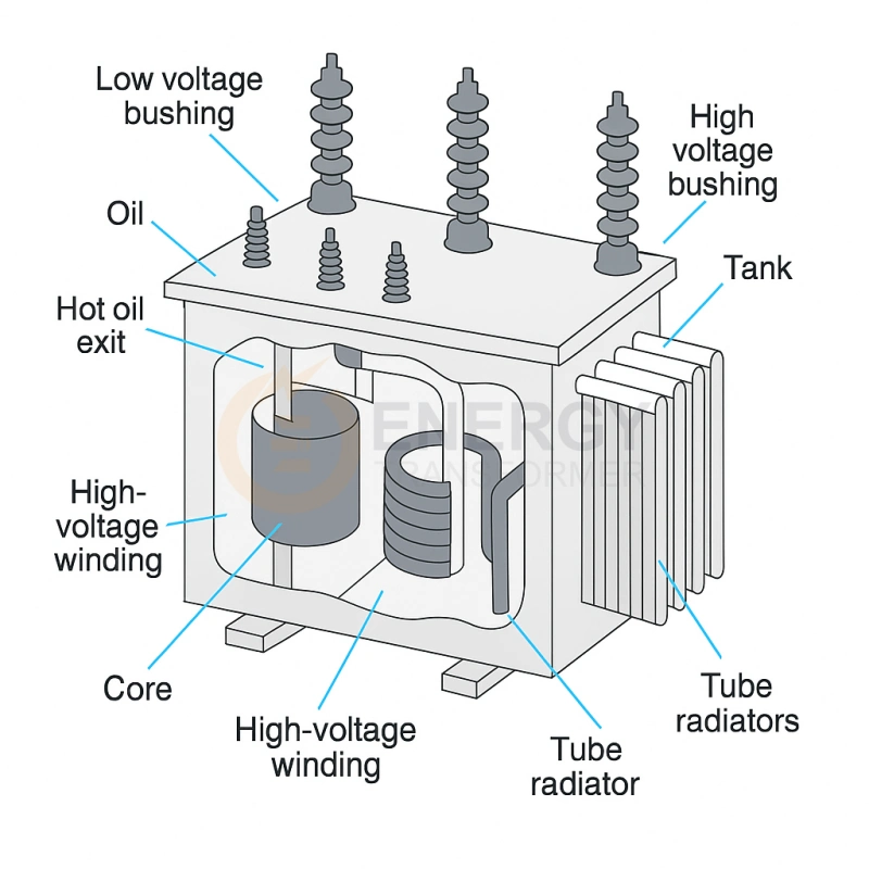
Tank: The Protective and Cooling Enclosure:
-
Structure: Steel enclosure housing the active part (core + windings) and insulating fluid (in oil-filled types).
-
Key Components & Systems:
-
Conservator: Expansion chamber for oil, connected to atmosphere via a breather (containing silica gel or activated alumina - open type), or using a nitrogen blanket/sealed system (sealed type). Modern designs favor membrane/air-cell sealed systems.
-
Cooling System:
-
Radiators: Natural oil circulation, natural air (ONAN).
-
Fans: Forced air cooling (ONAF - Oil Natural Air Forced / OFAF - Oil Forced Air Forced).
-
Pumps: Forced oil circulation (OFAN - Oil Forced Air Natural / OFAF / ODAF - Oil Directed Air Forced).
-
Coolers: Water cooling (OFWF - Oil Forced Water Forced) or directed oil flow (ODAF / ODWF).
-
-
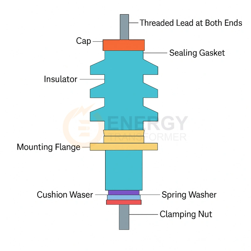
Bushings: Critical External Interface! Safely route internal HV/LV winding leads through the grounded tank wall to external lines. Classified by insulation:
-
Oil-Impregnated: Traditional, reliable, for high voltages.
-
RIP (Resin-Impregnated Paper) / RBP (Resin-Bonded Paper): Dry-type bushings, fire-resistant, explosion-proof, low maintenance, increasingly common.
-
Capacitive Graded: Incorporate conductive layers to evenly distribute electric field stress, essential for high voltages.
-
-
Protection Devices:
-
Buchholz Relay: Mounted in the pipe between conservator and tank. Alarms or trips on gas accumulation (minor faults) or sudden oil surge (major faults).
-
Pressure Relief Device (PRD): Rapidly opens to vent excess pressure caused by severe internal faults or overheating, preventing tank rupture.
-
Sudden Pressure Relay (SPR): Detects rapid pressure rises within the tank (e.g., arc faults), acting faster than a Buchholz relay.
-
-
Monitoring Devices: Oil level gauge, Winding Temperature Indicator (WTI), Oil Temperature Indicator (OTI), online monitors (DGA - Dissolved Gas Analysis, FRA - Frequency Response Analysis).
-
-
Read More:Basic Transformer Ratings Explained kVA, Voltage, Frequency & Impedance for Buyers and Engineers
IV. Losses and Efficiency: The Cost of Energy Conversion
-
Core Losses (No-Load Losses): Exist in the magnetic core whenever the primary is energized.
-
Hysteresis Loss: Energy dissipated as heat due to friction during the cyclic reversal of magnetic domains in the core material. Proportional to frequency
fand the area of the hysteresis loop (material dependent, related to peak flux densityB_max).P_h ∝ f * B_max^n(n≈1.6-2.0). -
Eddy Current Loss: Resistive loss (
I²R) from circulating currents induced in the core by the alternating flux. Proportional to the square of frequency (f²), the square of peak flux density (B_max²), and the square of lamination thickness (t²).P_e ∝ f² * B_max² * t². Thin, insulated laminations are crucial. -
Anomalous (Excess) Loss: Loss related to domain wall movement dynamics, usually smaller.
-
-
Copper Losses (Load Losses): Exist in the windings, increasing with load current (proportional to current squared
I²).-
DC Resistance Loss (
I²RLoss): Ohmic loss due to current flowing through the conductor resistance.P_cu_dc = I₁²R₁ + I₂²R₂. -
AC Resistance Loss (Eddy & Circulating Current Loss): Additional loss due to increased effective resistance from skin effect (current crowding at conductor surface) and proximity effect (mutual influence of adjacent conductors) under AC conditions. Significant in large transformers, mitigated using transposed conductors or continuously transposed cable (CTC).
-
-
Stray Losses: Eddy current losses in structural components (tank walls, frames, bolts) caused by leakage flux. Reduced by magnetic shunts and non-magnetic materials.
-
Efficiency: Ratio of output power (
P_out) to input power (P_in).η = (P_out / P_in) * 100% = [P_out / (P_out + P_core + P_cu + P_stray)] * 100%. Modern large power transformers achieve efficiencies exceeding 99.7%. High-efficiency design is a constant pursuit.
V. Modern Transformer Trends
-
Digitalization & Smart Grid Integration: Embedding sensors (temp, vibration, partial discharge, DGA, FRA) for real-time condition monitoring, predictive maintenance, fault diagnosis, and life assessment (Digital Twin concept).
-
Enhanced Reliability & Resilience: Stricter adherence to short-circuit withstand standards (IEC 60076-5), advanced diagnostic tools, robust mechanical design, redundancy strategies.
-
Eco-Design & Sustainability:
-
Replacing mineral oil with synthetic ester fluids (higher fire point, biodegradable).
-
Utilizing Fluorine-Free Fire-Fighting Fluids (FFFK) in installations.
-
Low-noise designs (acoustic barriers, optimized core clamping).
-
Focus on Life Cycle Assessment (LCA) and reduced carbon footprint.
-
-
Advanced Materials:
-
Amorphous Metal: Core material offering 60-80% lower no-load loss than CRGO, ideal for highly efficient distribution transformers.
-
High-Temperature Superconducting (HTS) Windings: Potential for revolutionary efficiency gains (near-zero resistance) and power density (under development/prototype stage).
-
Nanocomposite Insulation: Materials engineered with nanoparticles to enhance thermal conductivity, dielectric strength, and partial discharge resistance.
-
Conclusion
Theelectrical transformer stands as a perfect crystallization of electromagnetic theory in engineering practice. From the foundational principle of mutual induction based on Faraday's Law, to the meticulously designed core, windings, insulation system, cooling, and protection apparatus, every technological advancement aims to enhance its efficiency, reliability, and environmental sustainability. Understanding its working principles, loss mechanisms, and core construction is not only essential knowledge for electrical engineers but is also pivotal for driving power systems towards greater intelligence, efficiency, and environmental responsibility. As new materials, manufacturing processes, and digital technologies continue to emerge, this century-old cornerstone of electrical engineering will remain indispensable in the ongoing energy transition.